Showing posts with label Directional Drilling. Show all posts

Monday, February 1, 2016

Pipe Rotation Effect For Hole Cleaning For Water Based Drilling Fluid in Horizontal & Deviated Wells

This article written by Technology Editor Dennis Denny, contains highlights of paper SPE 114965 "Pipe Rotation Effect For Hole Cleaning For Water Based Drilling Fluid in Horizontal & Deviated Wells", by M.E. Ozbayoglu, Middle East Technical University; A. Saasen, Middle East Technical University; and K. Svanes, StatoilHydro, prepared for the 2008 IADC/SPE Asia Pacific Drilling Technology Conference and Exhibition, Jakarta, 25-27 August. The Paper has not been peer reviewed. 


Directional Drilling

What is Directional Drilling?
Directional drilling is the science of deviating a wellbore along a planned path to a target located at a given lateral distance and direction from vertical. This includes drilling as vertically as possible from a given TVD.
The figure below shows a vertical well and a deviated well.
As a starter one can consider that any well which gets deviated from the vertical axis to achieve the desired target (hydrocarbon reserve in our case) may be termed as deviated well (or Directional well). 


Vertical Versus Deviated Wells

What are the applications of Directional Drilling?

1. Side Tracking
Sidetracking is one of the primary uses for directional drilling. Sidetracking is an operation which deflects the borehole by starting a new hole at any point above the bottom of the old hole as in Figure below. 

The primary reason for sidetracking is to bypass a fish which has been lost in the hole; however, there are several other reasons for sidetracking. A sidetrack can be performed so the bottom of the hole can intersect a producing formation at a more favorable position such as up dip above the oil-water contact. A well can be sidetracked to alleviate problems associated with water or gas coning. A sidetrack can be performed in an old well to move the location of the bottom of the hole from a depleted portion of the reservoir to a portion that is productive, such as, across a fault or permeability barrier. 

Most often, a sidetrack is accomplished by setting a cement plug in the hole and dressing off the plug to a depth at which the sidetrack will commence. The sidetrack can be either "blind" or "oriented". In a blind sidetrack, the direction of the sidetrack is not specified and is not considered a directional well. In either case, a deflecting tool is used to drill out the old hole and start a new hole.
2. Straight Hole Drilling
straight hole drilling
may be a special case of directional drilling where an try is made out to keep the hole vertical. a few reasons for wanting out to keep the hole vertical are :
a.
out to keep from crossing lease lines ;
b.
out to keep among the specifications of the drilling contract ;
c.
out to keep among the well spacing requirements because we are part of a developed field 
3. Controlled Directional Drilling
Controlled directional drilling is used when drilling multiple wells from an artificial structure such as offshore platforms, drilling pads, or man made islands. The economics of building one offshore platform for each well would be prohibitive in most cases. However, since wells can be directionally drilled, forty or more wells can be drilled from a single platform. Without controlled directional drilling, most offshore drilling would not be economical.
 
4. Drilling Multiple Sands With One Wellbore
there will be special cases when multiple sands are drilled with one wellbore. where steeply dipping sand zones are sealed by an unconformity, fault, or salt dome overhang, variety of vertical wells might possibly be needed to actually manufacture every sand, which you ll realize are separated by a permeability barrier. in spite of this, all the sand zones often is penetrated with one directionally drilled well thereby greatly reducing the price of production 
5. Inaccessible Locations there will be occasions when oil deposits lie beneath inaccessible locations inclusive of towns, rivers, shorelines, mountains, or maybe even production facilities. each time a location can't be constructed directly higher than the manufacturing formation, the wellbore often is horizontally displaced by directional drilling. this allows production associated with an otherwise inaccessible hydrocarbon deposit  

6. Fault Drilling
directional drilling
can be applicable in fault drilling. it is typically troublesome to actually drill a vertical well because we are part of a steeply dipping, inclined fault plane. usually, the bit can deflect when passing in the fault plane, and typically the bit can follow the fault plane. to actually avoid the challenge, the well often is drilled upon the upthrown or downthrown side on your fault and deflected into your manufacturing formation. the bit can cross the fault at enough associated with an angle exactly where the direction on your bit can't amendment to actually follow the fault. 
7. Drilling Salt Dome Region several oil fields are associated when using the intrusion of salt domes. directional drilling has also been utilized tap a number of oil that has also been trapped by your intrusion on your salt. rather than drilling in the salt overhangs, the wells often is directionally drilled adjacent towards the salt dome and into your underlying traps as shown in figure below. in spite of this, since the event of salt saturated and oil based mostly muds, the level of directional drilling has decreased. it's troublesome to actually drill long intervals of salt with recent water muds. directionally drilling along the salt, alleviates a great deal of the issues related to drilling salt.  

8. Relief Well
a highly specialized application for directional drilling
is that the relief well. if a well blows out and is not accessible direct from surface, then a relief well is drilled to actually intersect the uncontrolled well close to the bottom. water or mud are then pumped in the relief well and into your uncontrolled well. since it is typically needed that the relief well intersect the uncontrolled well, the directional drilling has to actually be extremely precise and needs special tools. survey data isn't correct enough to actually intersect a wellbore at depth. proximity logging is needed when drilling relief wells. 
9. DRILLING HORIZONTAL WELLS
Horizontal drilling is another special application of directional drilling and is used to increase the productivity of various formations. One of the first applications for horizontal drilling was in vertically fractured reservoirs. In fractured reservoirs, a significant quantity of the production comes from fractures. Unless a vertical well encounters a fracture system, production rates will be low.
Horizontal drilling is used to produce thin oil zones with water or gas coning problems. The horizontal well is optimally placed in the oil leg of the reservoir. The oil can then be produced at high rates with much less pressure drawdown because of the amount of formation exposed to the wellbore.
Horizontal wells are used to increase productivity from low permeability reservoirs by increasing the amount of formation exposed to the wellbore. Additionally, numerous hydraulic fractures can be placed along a single wellbore to increase production and reduce the number of vertical wells required to drain the reservoir.
Horizontal wells can be used to maximize production from reservoirs which are not being efficiently drained by vertical wells.
10. Drilling Multilateral Wells
Directional drilling can also be used to drill multilateral wells. Multilaterals are additional wells drilled from a parent wellbore. Multilaterals can be as simple as an open hole sidetrack or it can be more complicated with a junction that is cased and has pressure isolation and reentry capabilities. Multilaterals are used where production can be incrementally increased with less capital costs. Multilaterals can be used offshore where the number of slots are limited. It is also used to place additional horizontal wells in a reservoir.
11. Extended Reach Drilling
Another application of directional drilling is what is commonly termed extended reach drilling. As illustrated in Figure below, extended reach drilling is where wells have high inclinations and large horizontal displacements for the true vertical depth drilled. Extended reach drilling is used to develop reservoirs with fewer platforms or smaller sections of a reservoir where an additional platform cannot be economically justified. Extended reach drilling will become more popular as the cost of platforms in deeper water and severe environments becomes more expensive.

16. DRILL COLLARS


The primary function of the drill collars is to provide sufficient WOB (Weight on bit). The weight of the collars also ensures that the drill pipe is kept in tension to prevent buckling.

Drill collars are heavy, stiff steel tubulars. They are used at the bottom of a BHA to provide weight on bit and rigidity. 

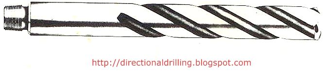
Flush or spiral drill collars are available. 

In directional drilling, spiral drill collars are preferable. The spiral grooves machined in the collar reduce the wall contact area by 40% for a reduction in weight of only 4%, thus reducing the chances of differential sticking.

The Spiral drill collars usually have slip and elevator recesses. Stress-relief groove pins and bore back boxes are optional.


SHORT DRILL COLLARS

Short Drill Collars (SDC's) are also called a pony collar.

It is simply a shortened version of a steel drill collar. 

Short drill collars may be manufactured or a steel drill collar may be cut to make two or more short collars. 

For a Directional Driller, the SDC and the short non-magnetic drill collar (SNMDC) have their widest application in the make-up of locked BHAs. SDCs of various lengths (e.g. 5’, 10’, 15’) are normally provided by the DD company.

NON-MAGNETIC DRILL COLLARS (NMDC)

Non-magnetic drill collars are usually flush (non-spiral). 

They are manufactured from high-quality, corrosion-resistant, austenitic stainless steel. 

Magnetic survey instruments (MWD / Magnetic Single Shots / Multi Shots) run in the hole need to be located in a non-magnetic drill collar of sufficient length to allow the measurement of the earth’s magnetic field without magnetic interference.
 
Survey instruments are isolated from magnetic disturbance caused by steel components in the BHA and drillpipe.

SHORT NON-MAGNETIC DRILL COLLARS (SNMDC) 

SNMDC is a short version of the NMDC.

They are often made by cutting a full-length NMDC.
 
The SNMDC may be used between a mud motor and an MWD collar to counteract magnetic interference from below. 

It is also used in locked BHAs, particularly where the borehole's inclination and direction give rise to high magnetic interference. 

Finally, BHAs for horizontal wells often use a SNMDC. 

The amount of bending a drill collar can undergo will depend on the material and the dimensions of the collar. 

The stiffness of the collar is the product of the collar's moment of inertia (I) and the modulus of elasticity for that material (E).

The moment of inertia (I) for a hollow cylindrical pipe is given by :
I = Π (D4 – d4) / 64
Where :
I = Moment of Inertia (in inch4)
D = Outside diameter (in inches)
d = Inside diameter (in inches) 

The modulus of elasticity for various materials can be obtained from manufacturer's specifications.
E.g. for steel E = 29 X 106 psi; for aluminium E = 11 X 106 psi; for monel E = 26 X 106 psi. 
Thus, an aluminium drill collar will be more flexible than a steel drill collar of similar dimensions.

IMAGES :

Flush Drill Collar

Non-Magnetic Drill Collar

Non-Magnetic Drill Collars


Spiral Drill Collars

Used Spiral Drill Collars
Drill Collar Manufacture Process


 (Click on the image for a high resolution)

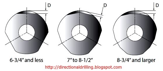
Figure below shows the cross sections of the drill collars and the reduced contact area with the wall of the hole.


Spiral Drill Collar Typical Size :

Note: Note: Loss of weight is approximately 4% compared to slick drill collars. Length of spiralled section allows reconditioning of connections.

Drill Collar Material Table : 


Elevator and Slip Recess Specification :
Drill Collar Data - 2-7/8” - 6-1/2” :


Drill Collar Data - 6-3/4” - 11-1/4” :


 BLOG ENDS

15. Rotary Assemblies - Building Assembly, Holding Assembly and Dropping Assembly

Rotary Assemblies, as the name suggests, the assemblies which are driven by rotary table at the surface. Actually these are the bottom hole assemblies (BHA's) designed to drill a well directionally (build or hold or drop) without the use of downhole motors.

The designing of the various rotary assemblies is based on the principle that as we shorten the active length of drill collar, it gives rise to fulcrum effect (which helps in building), when we increase the active length of drill collar it gives pendulum effect (which helps in dropping, condition: optimum WOB) and the combination of the two principle gives rise to holding.

Various Rotary Assemblies have been designed till date by placing stabilizers at various positions in a BHA and observing the result thus produced.

Here I am to going to discuss few such Assemblies which are useful in building, holding and dropping the inclination of a wellbore.

A question arises here is that when we have downhole motors easily available, then whats the need of using such old techniques !
So, I should tell you that the Operator companies proving Direction Drilling Service charges for the their tool on either day rate basis or hourly basis. Since the rental charges for downhole motors along with the survey tools (MWD/ LWD) becomes a costly affair, rotary assemblies are prefered after the well is kicked off or after acheiving a desired trajectory.
Its all upto you to decide whether at a prevailing situation the Rotary Assembly would be more cost effective or a downhole motor !
Figure below shows some of the common rotary assemblies currently being used :

Building, Holding and Dropping Assemblies
Lets kick off our discussion with Building Assembly ..

BUILDING ASSEMBLY

As said above, building assembly works on fulcrum principle.

It is used after the well is kicked off using a deflection tool to eliminate the use of expensive downhole mud motors. 

Here we use a near bit stabilizer which acts as a pivot or fulcrum for the lever. The drill collar portion above the near bit stabilizer to the first point of contact with the lower side of the wellbore acts as lever.

As we apply WOB, the bit is pressed towards the high side of the hole due to fulcrum effect and thus increases the inclination.

Now, here is something interesting : As we increase the WOB, there is bending of drill collar and the first contact point of drill string above the stabilizer with wellbore slides downwards. This results in decrease in lever length or "a decrease in active drill collar length". As I have discussed above, as the active drill collar length reduces, it increases the fulcrum effect and thus we get higher building rate.

Thus, an additional string stabilizer can be used to reduce the length of lever and hence increasing the build rate.

The addition of stabilizers other then the near bit stabilizer (NBS) modifies the build rate to match the required well trajectory.

Assemblies A and B respond well in soft or medium formations.

The inclusion of an undergauge stabilizer in assembly C will build slightly less angle. By bringing the second stabilizer closer to the near-bit stabilizer, the building tendency is increased.

In hard abrasive rocks, the problems of bit wear are significant.

To maintain gauge hole, the near-bit and second stabilizer should be replaced by roller reamers.

The build rate should be kept below 2° per 100 ft to reduce the risk of dog-legs.

The amount of WOB applied to these assemblies will also affect their building characteristics.

Too much WOB will cause rapid build-up of angle.

Typical building assemblies (A,B,C) are shown in the figure above.

NOTE : 30 FEET = 1 SINGLE OF DRILL COLLAR

HOLDING ASSEMBLY OR PACKED ASSEMBLY


The holding or packed assembly uses packed hole stabilization principle to maintain the inclination and direction.
Once the inclination has been built to the required angle, the tangential section of the well is drilled using a holding assembly OR packed assembly. The object here is to reduce the tendency of the BHA to build or drop angle. Actually this is dificcult to acheive, since formation effects and gravity may alter the hole angle.

The packed BHA relies on the principle that two points will contact and follow a sharp curve, while three points will follow a straight line as shown below :

                               Two Point contact          Three Point Contact                                    

To eliminate building and dropping tendencies, stabilizers should be placed at close intervals, using pony collars if necessary.

Assembly D in figure above has been used successfully in soft formations.

The undergauge stabilizer in assembly E builds slightly to counter gravity.

In harder formations the near-bit stabilizer is replaced by a reamer.

Generally only three stabilizers should be used, unless differential sticking is expected.

Changes in WOB  will not affect the directional behaviour of this type of assembly, and so optimum WOB can be applied to achieve maximum penetration rates.

Note : A packed hole assembly with several stabilizers should not be run immediately after a downhole motor run.

DROPPING ASSEMBLY OR PENDULUM ASSEMBLY

As I said earlier, Dropping Assemblies are based on pendulum principle. The pendulum technique is used to drop angle especially on high angle wells where it is usually very easy to drop angle.The pendulum technique relies on the principle that the force of gravity can be used to deflect the hole back to vertical. 

In directional wells, only an S shape profile requires a planned drop in angle. The other application of a dropping assembly is when the inclination has been increased beyond the intended trajectory and must be reduced to bring the well back on course.

It is best to drop angle in a section of softer formation, since the response to a pendulum type assembly in hard rock is very slow.

Figure above gives some typical dropping assemblies (F and G).  These are more effective in high-angled holes. If hole angle does not reduce, the WOB can be reduced, although this will also reduce the penetration rate.

BLOG ENDS

14. Pendulum Effect of Drill Collar Towards Hole Deviation

Here I am going to discuss about the Pendulum Effect, its mechanism and the forces acting, thus causing the drill bit along with active string to tend towards the lower side of wellbore.

Pendulum effect is the effect which tends to bring the drill bit along with the active string to the lower side of hole.
Consider the figure below:

Here,
W1 = Weight of bit along axis of drill collar
W2 = Component of W1 along axis of hole
W3 = Component of W1 along normal to hole axis
W4 = Vertical force of active drill collars assembly
W5 = Component of W4 acting along axis of assembly
W6 = Component normal to W5 but opposite to W3 

The effect of gravity on mass of drill collars above the bit is vertically downward (W4).
A part of this force is transmitted to the bit along the axis of assembly W5.
The complimentary component of this part W6 acts towards perpendicular to the axis of the assembly. It is supported by formation at the wall contact point at the bit. The influence of this lateral force at bit is always to reduce inclination and it's magnitude, automatically increases with inclination. If desired we can enhance the effect by increasing the active drillstring length the natural hole straightening tendency can usually be employed to avoid excessive inclination in vertical holes.


Formation dips also influences the hole deviation. For laminated formation when dips are less than 45 degrees the bit tries to drill perpendicular to bedding plane, and if it is in excess of 45 degrees bit tends to drill parallel to bedding plane. Likewise formation attitudes also have effect on directional tendencies. If proposed direction is due to up dip it follows the natural bit tendencies and drift angle can be readily built If proposed direction is due to up dip, it follows the natural bit tendencies and drift angle can be readily built. If the proposed direction is in left of up dip the bit will try to turn to right and if proposed direction is in right of up dip the bit will deviate to left. 

Bit drilling up dip where formations are dipping at angles less than 45 Degrees

Bit drilling up dip where formations are dipping at angles greater than 60 degrees

12. Woods, Lubinski, Hotch and Treicher's Theory on Deviated Holes

HENRY WOODS & ARTHUR LUBINSKI'S THEORY

Henry Woods and Arthur Lubinski stated in 1954 that the size of drill collar just above the bit is the limiting factor for the lateral movement of bit causing hole deviation.
They gave a formula to calculate the Minimum Effective Hole Diameter (MEHD) for lowering the casing. The formula is:

MEHD = (Bit Size + Drill Collar OD) / 2


ROBERT S. HOTCH'S THEORY

Later, Robert S. Hotch came up with a theory that while drilling with an unstabilized bit an abrupt change of hole angle can occur if hard ledges are encountered.
With reference to his theory, he suggested that the minimum permissible drill collar OD should always be greater than twice the casing coupling diameter to be run minus the bit size.

i.e. Minimum Drill Collar OD = 2 x Casing Coupling OD – Bit size

H.E. TRIECHER'S THEORY

At the Same time, H.E. Triecher pointed out that the lateral movement of an unstabilized bit in non dipping formation tends to cut a spiral hole. The spiralling will be more severe in soft formations where penetration rate is high and this will produce a hole of reduced drift diameter.

8. MWD/ LWD/ DD SERVICE COMPANIES IN THE WORLD

Below you will find links to companies in the world which provides the following services and products:


LIST OF MWD/LWD/DD SERVICE COMPANIES IN THE WORLD


In this list I include all types of directional drilling which consist of Oilfield Directional Drilling, Utility Installation Directional Drilling (or H.D.D., Horizontal Directional Drilling, Directional Boring) and in-seam directional drilling (Coal-Bed methane).


Canada
Ark Directional Services – http://www.arkdirectional.com
Atlantic Directional Inc. – http://www.atlanticdirectional.com
Axis Energy Services – http://www.axisenergyservices.com
Cathedral Energy Services – http://www.cathedralenergyservices.com
Compass Directional Services – http://www.compassdirectional.com
D&R Directional – http://www.drdirectional.com
Kambi MWD Services – http://www.kambi.ca
Meridian Directional Services – http://www.meridiandirectional.com
Motorworks Drilling Solutions – http://www.pure-energy.ca
Newsco Directional and Horizontal Drilling Services – http://www.newsco.ca
Pacesetter Directional Services – http://www.ppdl.ca
Phoenix Technology – http://www.phoenixcan.com
Pro-Line Directional – http://www.prolineenergyservices.com
OilField Guidance – http://oilfieldguidance.com
Ryan Energy Technologies / Nabors – http://www.nabors.com
Savanna Energy Services – http://www.savannaenergy.com
Ember Resources – http://emberresources.com
Extreme Engineering – http://www.extremeeng.com
Mostar Directional Technologies – http://mostardirectional.comBlackstone Drilling Systems – http://blackstonedrillingsystems.com/


United States of America
Scientific Drilling International – http://www.scientificdrilling.com/
Black Viper Energy Services Ltd. – http://www.blackviperenergy.com
Crescent Directional Drilling – http://www.crescentdirectional.com
Directional Drilling Company – http://www.directionaldrillers.com
Multishot Directional – http://www.multi-shotllc.com
RPM – http://www.rpm-inc.org
Strata Directional – http://www.alchenergy.com/directional.html
Quantum Drilling Motors – http://www.quantumdm.com
Native Navigation – http://www.nativenavigation.com
Pathfinder Energy Services – http://www.pathfinderlwd.com
Total Directional Services – http://www.totaldirectional.com
Drill Right Technology, Inc. – http://www.drillrighttechnology.com
Maverick Directional Services – http://www.maverickdirectional.com
Professional Directional – http://prodirectional.com
Intrepid Directional Drilling – http://www.intrepid-dds.com
Laney Directional Drilling – http://www.laneydrilling.com
Southeast Directional Drilling – http://www.southeastdrilling.com/
International Directional Services – http://www.idirectionaldrill.com
Directional Drilling Contractors – http://www.ddcon.com
PDI Construction – http://www.pdiconstruction.com
Henniker Directional Drilling – http://www.hddbore.com/
DayStar Directional Drilling – http://www.daystardrilling.com/
Sharewell Energy Services LP – http://sharewell.com
Target Drilling – http://www.targetdrilling.com
Associated Directional Drilling – http://aei-corp.com/add.html
Challenger Drilling Inc. – http://www.challengerdrilling.com/
Drake Directional Drilling – http://www.drakedd.com/
Spring and Associates, Inc. – http://www.springandassociates.com/
Ventura Directional Drilling – http://www.venturadrilling.com/
Magnum Drilling Services – http://www.magnumdrillingservices.com/
We-Bore-It – http://www.we-bore-it.com/
OnCourse, Inc. – http://www.oncourseinc.com/
WellBenders Directional Services – http://www.wellbenders.com/
Downhole Navigator – http://dhnavigator.com/
Cudd Energy Services – http://www.cuddpressurecntrl.com/
Boreview Services – http://boreview.com/


Europe
Transmark-EDS – http://www.edsnl.com/
Directional Drilling UK – http://www.directionaldrillinguk.com
Target Well Control – http://www.target-energy.com/
LMR Drilling UK – http://www.lmrdrilling.co.uk
Allen Watson – http://www.allenwatson.com
SW Directional Drilling – http://www.swdirectionaldrilling.co.uk
LMR Drilling GmbH – http://www.lmr-drilling.de/


Australia/New Zealand
SADB Directional Drilling – http://www.sadirectional.com.au
Ancon Directional Drilling – http://www.ancondrilling.com
Mitchell Directional Drilling – http://www.mitchelldrilling.com/directional/
SJ Directional Drilling P/L – http://www.sjdirectionaldrilling.com.au
Hartowijaya – http://www.hartowijaya.com
Wellserv Australia – http://wellserv.com.au


China/Hong Kong
WellTech – China Oilfield Services Limited – http://www.cosl.com.cn


Indonesia
Qui Handika – http://www.quihandika.com
Pakarti/Parama – E-mail: pandu@paramaservices.com


Nigeria
Avionix Energy Ltd. – http://www.avionixenergy.com


Middle East/North Africa
National Drilling Services – http://www.ndsye.com/
Intelligent Drilling Services – http://intelligentdrilling.com/
Triple L Oil Services – http://www.triplel-tlos.com/
AlMansoori Directional Drilling Services – http://www.almansoori.biz/


India
Jindal Drilling & Industries – http://www.jindaldrilling.com/
Shiv-Vani – http://www.shiv-vani.com/


Central/South America
Integradora de Perforaciones y Servicios – http://ips-mexico.com/
INVAP – http://www.invap.net/
San Antonio Internacional – http://www.sanantoniointernacional.com/


LIST OF REAL-TIME DRILLING DATA SERVICE COMPANIES

Petrolink – http://www.petrolink.com
Epoch Rigwatch – http://www.epochwellsite.com/
NOV MD-Totco Rigsense – http://www.nov.com/
Pason – http://www.pason.com/
PetroDAQ – http://www.petrodaq.com/
Wellsite Data Solutions – http://wellsite-ds.com/
OilField Guidance’s MWDLive – http://www.mwdlive.com/


LIST OF GEOSTEERING SERVICE COMPANIES

GeoSteering Services – http://www.geosteering.com/
United Oil & Gas Consulting – http://www.uogc.com/