Dedicated to : Mr. APS Gill, Mr. Munir Alam, Mr. S Suman & Mr. Chandrashekhar Mallik , Directional Drilling Team, ONGC Limited, Mehsana Asset, INDIA
----------------------------------------------------------------------------------------------
In directional wells we usually drill vertically upto the kick-off point (KOP).
From the KOP the well is deflected towards the target.
While planning a directional well we determine an angle and a direction in which the well is to be kicked off.
I hereby furnish my experience of kick off operation gained at a Horizontal directional well at Location No. :SNHK, drilled at Santhal Oil Field, Cambay Basin of Western Onshore, India.
Operator: Oil and Natural Gas Corporation Ltd., India
Directional Drilling Service Provider: M/s Weatherford Oil Tool Middle East Ltd.
 |
| Fig 20.1 General Well Data |
Note: The Excel sheet has been manually developed by Deepak Choudhary for Academic Purpose.
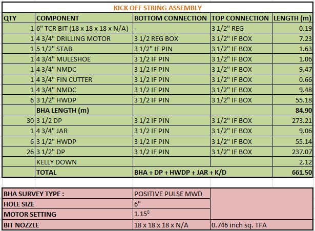 |
| Fig 20.2 Kick off String Assembly |
Operation Report :
M/Arrangement & R/I with above BHA along with MWD tool assembly upto 661.50 m against planned 687.00 m.
Circulated to condition mud at 661.5 m.
Stopped circulation and conducted survey at bottom keeping the string in satic condition.
The survey reading gives us the value of inclination, azimuth and toolface.
It should be noted that for angle less than 3 or 5 degree, the tool gives us MAGNETIC TOOL FACE.
These survey readings are displayed on the MWD Rig Floor Display Unit and looks like shown in figure below:
 |
| Fig 20.3 MTF indication at MWD Rig Floor Display Unit |
Now after the survey is conducted, we observed that that MTF is 40 degree.
It is to be noted at the MTF and Azimuth are same, i.e. wrt true North. So by adjusting the MTF we can kick of the well at our required azimuth which is 189 degree.
So in order to bring MTF to 189 degree, the scribe line of the motor should be rotated by an angle of 149 degree (= 189 - 40) towards right (clock-wise).
Once the required toolface setting has been determined (i.e. 149 degree), the effect of reactive torque must be considered.
Reactive torque is the twisting effect caused by the stator of the downhole motor turning anticlockwise in response to the rotor turning clockwise.
The amount of twisting depends on the physical properties of the motor, the length of the drill string and the formation characteristics.
Motor manufacturers provide estimates of how much left-hand turn can be expected under certain situations. From these tables, or from experience of drilling with similar tools in similar formations, the directional driller must compensate for reactive torque by deliberately pointing the tool face to the right of the calculated heading.
As soon as the bit begins to drill, the scribe line will turn to the left to bring it
back to the calculated heading. The amount of WOB will also affect the reactive torque. As the bit drills off, the reactive torque will reduce.
back to the calculated heading. The amount of WOB will also affect the reactive torque. As the bit drills off, the reactive torque will reduce.
In our case, the result of reactive torque was estimated to be about 20 degree.
So, net right turn to be provided = MTF Correction (149)+Reactive torque (20)
Thus to make a 149 degree incriment in MTF, we need to rotate the whole system by 169 degree right (i.e. clockwise).
Now we take into consideration the Bit walk. Bit walk is the tendency of the bit to wander off course by following the direction of rotation (usually to the right).
Let us consider 10 degree as a correction factor to maintain the deviation tendency due to bit walk.
So now from 169 degree we have to reduce 10 degree to adjust the bit walk tendency.
Finally, we are left with 159 degree.
To do so, we make a reference marking on rotary table and other marking which is 159 degree to right of rotory table marking on the floor using chalk.
Note: the two markings should be visible to the driller as he is the one who is going to rotate the rotary table.
The marking made on the rotary table is as shown in the picture below :
 |
| Fig 20.4 Tool face Correction |
Now, by rotating the rotary table in clock wise fashion, we will coincide the two markings so that the whole system rotates by 159 degree right.
After the two markings coincide, it looks something like as shown in the figure below :
 |
| Fig 20.5 Tool face Correction |
After the markings coincide, we look at the MWD Rig Floor Display unit which keeps updating the tool face every 30 seconds.
Now the situation is that, the string is stationary and we are waiting for the tool face to be updated on Rig floor display unit.
We want the rig floor display unit to show the MTF to be equal to 179 degree exact wrt North (N).
It is to be noted that the reactive torque may vary. The data provided my Mud motor manufacturers and the estimate made by the directional driller are not always an exact data. It's an estimated one. So there might be some positive or negative error in the MTF reading which we are waiting for.
So the wait is over ... Here comes the updated tool face reading :
 |
| Fig 20.6 MWD Rig Floor Display Unit showing the corrected MTF |
The actual reading of 175 degree is practically obtained which is 4 degree less than the desired 179 degree.
We have a scope to correct this 4 degree difference in azimuth over the remaining course length. Therefore this difference of azimuth is not a harmful issue. It is suggested that there is no harm if kick off is performed at 175 degree azimuth and later correction may suitably be made for the said 4 degree.
KICK OFF TECHNIQUE
Now to kick off the well with azimuth = 175 degree, we lock the rotary table so that there is no rotational movement provided to the drill string which may disturb its tool face orientation.
The drilling is now performed by the mud motor, not by the kelly. At the derrick floor the whole system is stationary and the mud motor performs its drilling job at the bottom.
From the surface we continuously keep maintaining the desired WOB so that the further drilling by mud motor is continued. This process of drilling using mud motor by keeping the rotary table in locked condition is called SLIDING.
During kick off, our main motive is to initially provide a guided path to the BHA. Now what length to slide will depend on the type of formation being drilled.
In prevailing practice, slide in one stretch is done for 10-12m of MD. The decision of the length to be slided depends upon the consolidation of the formation being drilled.
In loose formation there is more risk of deviation, so the slide length is taken more than 2 drill pipe length.
In hard formation the deviation tendency is less, so even a single drill pipe length of slide is sufficient to guide the bit in a particular path.
The kick off operation is now over.
Based on his experience, the Directional Driller will decide to take further sliding or to switch over to rotary drilling.
 |
| Fig 20.7 Sliding using Mud Motor (Left) and Rotary Drilling (Right) |
Now our next objective is to check the result of our slide. It is to be noted that the MWD tool lies at about 20 m above the bit. This distance b/w the MWD tool and the Bit is called the tool offset. After we have slided for say 12 m, the drilled depth is 661.5+12 =673.5 m. The position of bit is now at 673.5 m and the MWD tool is 20 m above the bit, i.e. at 653.5 m.
When the drilled depth will be 673.5+20=693.5 m, the position of MWD tool will be at the end of slide, i.e., at 673.5 m.
Now we can take survey to check the result of our sliding action.
Survey Procedure :
- Stop Rotary.
- Bring String 3-4 m off bottom.
- Circulate out cuttings.
- Shut off pump and confirm that Pump Down Time at MWD Rig Floor Display unit declines to zero. It indicates that the pump discharge is zero.
- Now concentrate at Pump Up Time at MWD Rig Floor Display unit. It keeps on increasing which indicates the time for which the pump had been kept shut off (no discharge observed).
- It is worth mentioning that it takes about 2 -3 minutes for the display of survey data at MWD Rig Floor Display unit.
- Record the Survey data.
The case data is furnished as below :
 |
| Fig 20.6 Survey Sheet |
Note: The Excel sheet has been manually developed by Deepak Choudhary for Project Report Purpose.
In the table, the survey readings at 693.15 m MD is the result of 12 m slide. This also indicates that the slide was properly performed and has given the desired result.
END OF THE BLOG