THIS BLOG IS DEDICATED TO MR. DP RAI, CHIEF ENGINEER (DRILLING), ONGC LTD., AHMEDABAD ASSET, INDIA
----------------------------------------------------------------------------------------------
Before answering the questions posted in the previous blog, I would like to share with you the objective behind writing this blog. While going through several books I found that the explanation given in the books are sometimes difficult to grasp or are of higher standard to the beginners. So my approach and the objective of writing this blog is to present the fundamentals of Directional Drilling in the simplest way possible. That's the only reason why I decided to start off with the fundamentals of conventional drilling.
So lets move ahead ..
Q1. What is Drilling?
In simple words, (In Oil & Gas industry) drilling can be defined as a process of making a hole below the earth surface using set of Drill Pipes (which are simply the steel pipes which are connected to one another to form a long string called Drill String) and Drilling bit. Here the function of drilling bit is to drill the formation so that we can move ahead in depth. The drilling operation is continued till we reach our target zone (which is the hydrocarbon reserve).
The drilling rig is a medium to support and hang the drill pipe and the mechanisms provided on the drilling rig helps to add another drillpipe to the present drill string, provide load on the bit so that we keep moving ahead in depth, helps rotating the drill string so that rotational force at bottom helps to drill the formation. There are several other functions which will be explained ahead.
The figure below presents a simplified view of the drilling operation.
Q2. Will be answered at the end.
Q3. What is a Drilling Rig?
Q4. What are the various components of drilling rig?
Q4. What are the various components of drilling rig?
A drilling rig is a structure used to create hole (usually called boreholes) in the ground.
They can be mobile equipment mounted on trucks, tracks or trailers, or more permanent land or marine-based structures.
Classification of Drilling Rig:
Classification of Drilling Rig:
A drilling rig has several components which together provides a driving force to drill ahead. Every component of the drilling rig has a specific function and equal importance.
A simplified figure of an onshore (land) drilling rig is shown below.
There are four major components of a drilling rig:
a. Hoisting System
b. Rotating Equipment
c. Circulating System
d. Power System
Now let us go through each of the above mentioned components in detail.
HOISTING SYSTEM
The hoisting system is used to raise and lower pipe in and out of the hole and to support the drill string to control the weight on the drill bit during drilling.
It consists of Crown Block, Derrick, Traveling Block, Drilling Line and Drawworks.
The derrick is a steel tower that is used to support the traveling and crown blocks and the drill string. There may be no more identifiable symbol of the oil and gas industry than the derrick on a drilling rig.
The crown and traveling blocks are a set of pulleys that raise and lower the drill string. The crown block is a stationary pulley located at the top of the derrick. The traveling block moves up and down and is used to raise and lower the drill string. These pulleys are connected via a large diameter steel cable called drilling line.
One end of the cable is connected to a winch or drawworks. The drawworks contains a large drum around which the drilling cable is wrapped. As the drum rotates one way or the other, the drilling cable spools on or off the drum and raises or lowers the drill string.
Look at the figure below. It clearly shows how the steel cable passes through the Crown block and Traveling block and its one end goes to the drawwork.
Now let us have a look at traveling block closely .. ! The pulleys of the traveling block can be easily seen the the picture below.
This is how actually the traveling block looks like when the pulleys are covered using a box :
Figure below shows a Crown Block. It sits on the crown platform, which is a steel platform located along the upper portion of the rig. The crown block works in conjunction with a similar component, the traveling block, which is positioned just below the crown platform. Together, these two systems are known as the block and tackle.
Each crown block consists of a series of pulleys and steel cables, or sheaves. These cables and pulleys sit on a steel frame, which may be built into the structure of the derrick. The sheaves serve as drilling lines, and pass through the traveling block below to connect to the rig's hoisting drum.
While the crown block itself is fixed and used to stabilize the sheaves, the traveling block moves up and down with the cables. This traveling block contains internal pulleys, which are surrounded by steel to protect both the pulleys and the cables from corrosion.
As said before, a key component of drilling rigs the drill line is made of multiple thread wounded wire ropes to be used for the lowering and raising of the drill string into and outside of the well bore. The drill line threads through the traveling and crown blocks.
If using a large size of line, it is possible to reach a million pounds of tension strength.
The function of a derrick is to provide the vertical clearance necessary to the raising and lowering of the drill string into and out of the hole during the drilling operations.
Derricks are rated according to their ability to withstand two types of loading:
1. Compressive loads
2. Wind loads
The allowable compressive load of a derrick is computed as the sum of the strengths of the four legs. Derricks with load capacities from approximately 86,000 to 1,400,000 lb, depending on steel grade and leg size are available.
Allowable wind loads for API derricks are specified in two ways, with or without pipe setback.
With pipe setback, the wind may be blowing perpendicular to it, which is essentially a pipe wall. This is the worst possible condition.
Wind loads are calculated by the formula:
P = 0.004V2
where P = wind load, lb/ft2
V = wind velocity, mph
Calculation of Derrick Loads
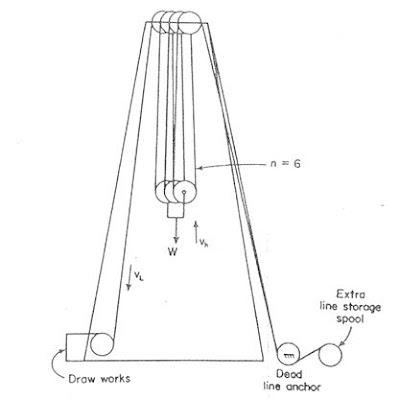
The block and tackle arrangement for a rotary rig is shown in Figure 4. Assuming that the system is frictionless, the following relationship are apparent:
Fd = total compressive load on the derick
n = number of lines through the traveling block (those supporting W).
W = hook load
The derrick load is always greater than the hook load by the the factor of (n+2)/2 due to the two additional lines (drawworks and anchor) exerting a downward pull.
Thus, the derrick load is a function of 'n'. More the value of 'n', less is the derrick load.
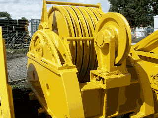
The drawworks or hoist is the key piece of equipment on a rotary rig.
The functions of the drawworks are:
a. It is the control center from which the driller operates the rig. It contains the clutches, chains, sprockets, engine throttles and other controls which enable the rig power to be diverted to the particular operation at hand.
b. It houses the drum which spools the drilling line during hoisting operations and allows feed-off during drilling.
where
W = Hook load, lb
vh = hoisting velocity of travelling block, ft/min
33,000 = ft.lb/min per horsepower
e = Hook to drawworks efficiency
Hook to drawworks efficiencies are commonly between 80 to 90% depending on the number of line in use.
The figure below summarizes the complete hoisting system.
ROTATING EQUIPMENTS
The rotating equipment turns the drilling bit. This equipment consists of the swivel, the kelly, the rotary table, the drill pipe, the drill collars, and the bit.
SWIVEL
The swivel allows the drill string to rotate while supporting the drill string's weight and providing a pressure-tight connection for the circulation of drilling fluid . The drilling fluid enters the swivel by way of the goose neck, a curved pipe connected to a high pressure hose. Connected to the swivel is a three-, four-, or six-sided 40 ft (12.2 m) length of hollow steel known as the kelly.
KELLY
The kelly is a square or hexagonal shaped section of pipe that is attached to the swivel. The kelly fits in a matching slot in the rotary table. As the rotary table turns the kelly is also turned. The movement of the kelly rotates the drill string and the drill bit.
The figure below shows a hexagonal kelly placed in the kelly bushing.
ROTARY TABLE
A rotary table is a mechanical device on a drilling rig that provides clockwise (as viewed from above) rotational force to the drill string to facilitate the process of drilling a borehole.
The kelly is inserted through the center of the rotary table and kelly bushings, and has free vertical (up & down) movement to allow downward force to be applied to the drill string, while the rotary table rotates it.
TO BE CONTINUED ...


Your blog provided us with valuable information to work with. Each & every tips of your post are awesome. Thanks a lot for sharing. Keep blogging,
ReplyDeleteמדביר מקצועי